Series AC3Power Factor Corrected
|
| 3 Phase Input Delta-Connection. Meets all specifications even with loss of one phase.
3 Phase Input Voltage: 208 VAC +/-20% (line to line), no neutral connection.
TYPICAL FEATURES/ELECTRICAL CHARACTERISTICS: AC Line Input Voltage: Three-Phase, 208 VAC +/-20% 47-440 Hz Output Voltage Ripple: 75-500 mV, See chart Operating Temperature: 0 to 85º C, case temperature. See application notes for proper thermal considerations. Availabe with -20°C and -40°C operating temperature range: Consult FactoryIsolation:
Current Limit Setpoint: 130 % of full load rating (Typical) Operating Frequency: 100Khz: Fixed |
|
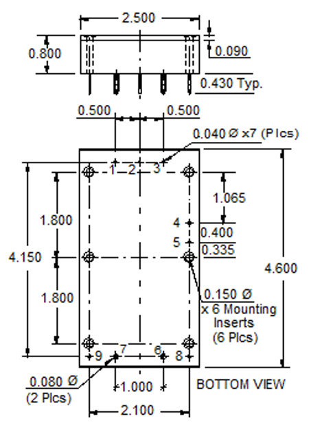
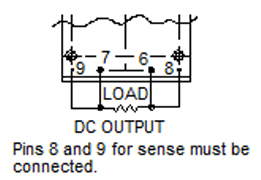
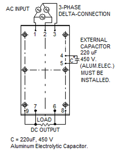
For Output Voltages of up to and including 48V
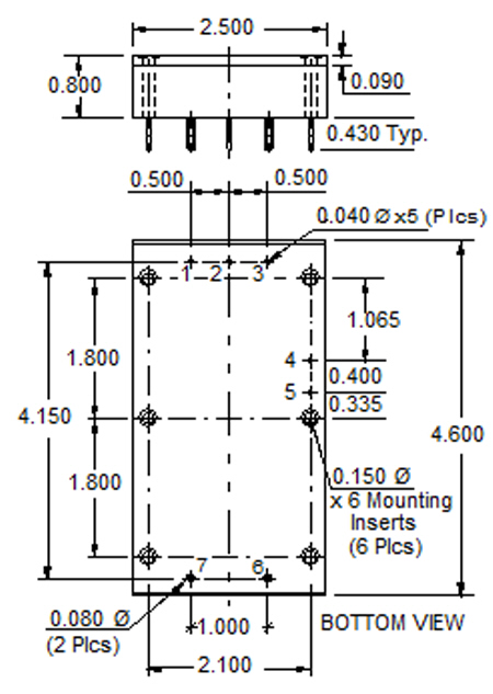
All dimensions are in Inches NOTE: The torque for mounting screws must be 6 to 9 In-Lbs. |
NOTE: Pins 8 and 9 are for models with output voltages up to and including 48 Volts. They are not on the higher voltage models (Those greater than 48 Volts) |
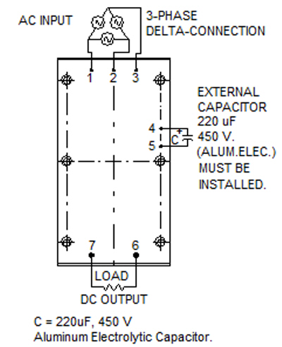
For Output Voltages over 48V
Weight: 340 Grams Typical |
| Pico Part No. |
Output Voltage VDC |
Max. |
Max. |
EFF @ Full Load (%)* |
Output Ripple Full Load 1-1 MHz BW mv p-p* |
Output Voltage Tolerance (±%)* |
V Ld. Reg 10-100% Load (±%)* |
Line Regulation (±%)* |
Price (US $) |
|---|---|---|---|---|---|---|---|---|---|
|
AC3-5S
|
5
|
30
|
150
|
76
|
100
|
1.0
|
1.5
|
0.2
|
416.11
|
|
AC3-9S
|
9
|
27.8
|
250
|
78
|
100
|
1.0
|
1.5
|
0.2
|
416.11
|
|
AC3-12S
|
12
|
25
|
300
|
80
|
150
|
0.5
|
1.5
|
0.2
|
416.11
|
|
AC3-15S
|
15
|
20
|
300
|
80
|
150
|
0.5
|
1.5
|
0.2
|
416.11
|
|
AC3-24S
|
24
|
12.5
|
300
|
81
|
250
|
0.5
|
1
|
0.2
|
416.11
|
|
AC3-28S
|
28
|
10.71
|
300
|
82
|
300
|
0.5
|
1
|
0.2
|
416.11
|
|
AC3-48S
|
48
|
6.25
|
300
|
82
|
500
|
0.5
|
1
|
0.2
|
458.42
|
|
AC3-100S
|
100
|
2.50
|
250
|
85
|
250
|
1.0
|
1
|
0.2
|
567.03
|
|
AC3-125S
|
125
|
2.00
|
250
|
85
|
250
|
1.0
|
1
|
0.2
|
567.09
|
|
AC3-150S
|
150
|
1.67
|
250
|
85
|
350
|
1.0
|
1
|
0.2
|
567.03
|
|
AC3-175S |
175
|
1.43
|
250
|
85
|
350
|
1.0
|
1
|
0.2
|
567.03
|
|
AC3-200S
|
200
|
1.25
|
250
|
85
|
400
|
1.0
|
1
|
0.2
|
610.57
|
|
AC3-225S
|
225
|
1.11
|
250
|
85
|
400
|
1.0
|
1
|
0.2
|
610.57
|
|
AC3-250S
|
250
|
1.00
|
250
|
85
|
500
|
1.0
|
1
|
0.2
|
610.57
|
|
AC3-275S
|
275
|
0.91
|
250
|
85
|
500
|
1.0
|
1
|
0.2
|
610.57
|
|
AC3-300S
|
300
|
0.83
|
250
|
85
|
500
|
1.0
|
1
|
0.2
|
653.32
|
|
External Capacitor Required: 220µF, 450 V Aluminum Electrolytic Capacitor |
|||||||||
|
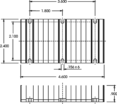
CH HEATSINK
|
CV HEATSINK
|
|
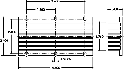
All dimensions are in inches ()=mm |
|
|
|
|
|
|
|
|
|
|
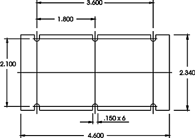
THERMAL INTERFACE
PART TI
Alloy Aluminum Substrate
Thermal Conductivity, (BTU-in/hr ft² ºF) ----1530
Coefficient of Thermal Expansion (25-100ºC, 10-6 in./in. ºF ---13.1
Hardness, Brinnell B ----23
Endurance Limit, psi. ----5000
Standard Thickness (inches) ---.002
Thermal Considerations
| AC3 Series | |||
|---|---|---|---|
|
|
|
CV |
|
| Free Air |
|
|
|
| 200 LFM |
|
|
|
| 400 LFM |
|
|
|
| 600 LFM |
|
|
|
| 800 LFM |
|
|
|
| 1000 LFM |
|
|
|
|
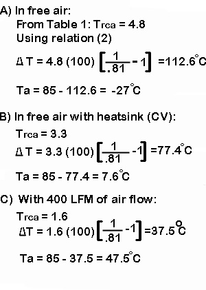
EXAMPLE 1:
|
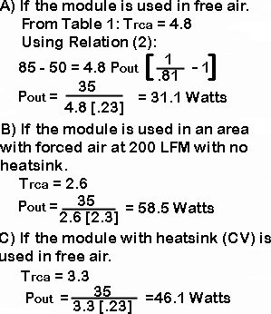
EXAMPLE 2:
|
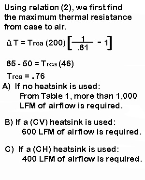
EXAMPLE 3:
|
|
For output voltages up to and including 48V
(see application note for remote sense) |
For output voltages above 48V
|
Remote Sense Terminals (only on models with output voltages below and including 48V)
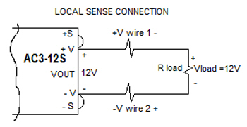
Remote Sense terminals must be connected for unit to operate properly. When conncected in local sense (+S connected to +V output terminal and -V output terminal), the output voltage is regulated at the output terminals.
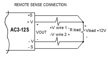
If your load is connected more than a few inches away from the unit and you want to regulate the output voltage ON the load, remote sense is required. This means connecting the +S connection at the end of the +V wire (at the load), and the -S connection at the end of the -V wire (at the load). Since the load wires have current flowing through them and they have a certain resistance, there will be a voltage drop in them so that the output voltage at the load will be lower than the output voltage of the unit. Remote sense will prevent theis by compensating for up to 1V of drop in the load wires. This means that the output voltage of the unit will ge up to 1V higher than the nominal value, so that at the load, the voltage will be the nominal value.
Example of local and remote sense connections, using the AC3-12S with a 0.2V drop in the wires connecting the +V and -V output terminals to the load
Vout = Voltage on the output voltage terminals of the unit.
Vload = Voltage on the load where the wires are connected.
Vout = Vload + Vwire1 + Vwire2
|
LOCAL SENSE CONNECTION
|
REMOTE SENSE CONNECTION
|
| With local sense, Vout is regulated at 12V So, Vout = 12V Vload = Vout - Vwire1 - Vwire2 Vload = 12V - .2V - .2V = 11.8 Volts |
With remot sense, Vload is regulated at 12V So, Vload = 12V Vout = Vload + Vwire1 + Vwire2 Vout = 12V + .2V + .2V = 12.4 Volts |
The voltage drops in the wires connecting the +V and -V output terminals of the unit and the load depend on the size of the wire (or PCBoard trace) and the current flowing through them.
For immediate engineering assistance or to place an order:
Call Toll Free: 800-431-1064
PICO Electronics, Inc.
143 Sparks Ave. Pelham, NY 10803
Tel: 914-738-1400
Fax: 914-738-8225

