
Features
- 0.99 (AC1) or 0.95 (AC3) Power Factor
- Single or three phase input
- Meets EN/IEC 610000-3-2
- 300W output power in a full brick size
- Input/output isolation
- Regulated 5V to 300V output models
- Output sense feature
- Fixed operating frequency
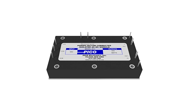
The AC series are isolated AC to DC power supplies with integrated power factor correction. The space saving 4.6″ x 2.5″ x 0.8″ full brick can power up to 300W. Output voltage models ranges from 5V to 300V. The combination of front end PFC module and isolated low voltage output saves space – one module instead of two modules.

Input Voltage Range (VAC)
Single Output Voltage (VDC)
Single Max Output Power (W)
| Part Number | Mounting | # of Outputs | Power Supply Type | Power Factor Corrected | Input Voltage Range (VAC) | Single Output Voltage (VDC) | Single Max Output Power (W) | Downloads |
|---|---|---|---|---|---|---|---|---|
| AC3-9S | Through Hole | Single | Switching | PFC | 165 – 250 (3Φ) | 9 | 250 | |
| AC3-5S | Through Hole | Single | Switching | PFC | 165 – 250 (3Φ) | 5 | 150 | |
| AC3-48S | Through Hole | Single | Switching | PFC | 165 – 250 (3Φ) | 48 | 300 | |
| AC3-300S | Through Hole | Single | Switching | PFC | 165 – 250 (3Φ) | 300 | 250 | |
| AC3-28S | Through Hole | Single | Switching | PFC | 165 – 250 (3Φ) | 28 | 300 | |
| AC3-275S | Through Hole | Single | Switching | PFC | 165 – 250 (3Φ) | 275 | 250 | |
| AC3-250S | Through Hole | Single | Switching | PFC | 165 – 250 (3Φ) | 250 | 250 | |
| AC3-24S | Through Hole | Single | Switching | PFC | 165 – 250 (3Φ) | 24 | 300 | |
| AC3-225S | Through Hole | Single | Switching | PFC | 165 – 250 (3Φ) | 225 | 250 | |
| AC3-200S | Through Hole | Single | Switching | PFC | 165 – 250 (3Φ) | 200 | 250 | |
| AC3-175S | Through Hole | Single | Switching | PFC | 165 – 250 (3Φ) | 175 | 250 | |
| AC3-15S | Through Hole | Single | Switching | PFC | 165 – 250 (3Φ) | 15 | 300 | |
| AC3-150S | Through Hole | Single | Switching | PFC | 165 – 250 (3Φ) | 150 | 250 | |
| AC3-12S | Through Hole | Single | Switching | PFC | 165 – 250 (3Φ) | 12 | 300 | |
| AC3-125S | Through Hole | Single | Switching | PFC | 165 – 250 (3Φ) | 125 | 250 | |
| AC3-100S | Through Hole | Single | Switching | PFC | 165 – 250 (3Φ) | 100 | 250 | |
| AC1-9S | Through Hole | Single | Switching | PFC | 85 – 265 | 9 | 250 | |
| AC1-5S | Through Hole | Single | Switching | PFC | 85 – 265 | 5 | 150 | |
| AC1-48S | Through Hole | Single | Switching | PFC | 85 – 265 | 48 | 300 | |
| AC1-28S | Through Hole | Single | Switching | PFC | 85 – 265 | 28 | 300 | |
| AC1-24S | Through Hole | Single | Switching | PFC | 85 – 265 | 24 | 300 | |
| AC1-15S | Through Hole | Single | Switching | PFC | 85 – 265 | 15 | 300 | |
| AC1-12S | Through Hole | Single | Switching | PFC | 85 – 265 | 12 | 300 |