
Features
- 120V to 1200V input range models
- 5V to 300V output models
- Up to 300W output
- Input/output isolation
- Remote Sense feature
- Input reverse polarity protection
- Fixed operating frequency
- No external components required
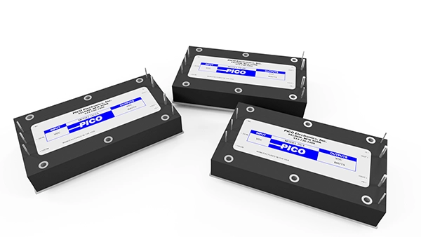
The DC1, DC2A & DC2B series are isolated DC-DC converters with a wide selection of input voltage ranges from 120V to 1200V and output power up to 300W. These modules have sense feature to accurately regulate the voltage at a remote load. Input is protected against reverse polarity.
The full brick case size has threaded inserts to mount securely for high vibration and shock applications. Conduction cooling is available through the baseplate or compatible heat sink.

Input Voltage Range (VDC)
Single Output Voltage (VDC)
Single Max Output Power (W)
| Part Number | Series | Mounting | # of Outputs | Temperature Range | Nominal Input Voltage (VDC) | Input Voltage Range (VDC) | Single Output Voltage (VDC) | Single Max Output Power (W) | Downloads |
|---|---|---|---|---|---|---|---|---|---|
| DC2B-9S | DC2B | Through Hole | Single | 0°C to +85°C Baseplate | 900 | 700 – 1200 | 9 | 250 | |
| DC2B-5S | DC2B | Through Hole | Single | 0°C to +85°C Baseplate | 900 | 700 – 1200 | 5 | 150 | |
| DC2B-48S | DC2B | Through Hole | Single | 0°C to +85°C Baseplate | 900 | 700 – 1200 | 48 | 300 | |
| DC2B-300S | DC2B | Through Hole | Single | 0°C to +85°C Baseplate | 900 | 700 – 1200 | 300 | 250 | |
| DC2B-28S | DC2B | Through Hole | Single | 0°C to +85°C Baseplate | 900 | 700 – 1200 | 28 | 300 | |
| DC2B-275S | DC2B | Through Hole | Single | 0°C to +85°C Baseplate | 900 | 700 – 1200 | 275 | 250 | |
| DC2B-250S | DC2B | Through Hole | Single | 0°C to +85°C Baseplate | 900 | 700 – 1200 | 250 | 250 | |
| DC2B-24S | DC2B | Through Hole | Single | 0°C to +85°C Baseplate | 900 | 700 – 1200 | 24 | 300 | |
| DC2B-225S | DC2B | Through Hole | Single | 0°C to +85°C Baseplate | 900 | 700 – 1200 | 225 | 250 | |
| DC2B-200S | DC2B | Through Hole | Single | 0°C to +85°C Baseplate | 900 | 700 – 1200 | 200 | 250 | |
| DC2B-175S | DC2B | Through Hole | Single | 0°C to +85°C Baseplate | 900 | 700 – 1200 | 175 | 250 | |
| DC2B-15S | DC2B | Through Hole | Single | 0°C to +85°C Baseplate | 900 | 700 – 1200 | 15 | 300 | |
| DC2B-150S | DC2B | Through Hole | Single | 0°C to +85°C Baseplate | 900 | 700 – 1200 | 150 | 250 | |
| DC2B-12S | DC2B | Through Hole | Single | 0°C to +85°C Baseplate | 900 | 700 – 1200 | 12 | 300 | |
| DC2B-125S | DC2B | Through Hole | Single | 0°C to +85°C Baseplate | 900 | 700 – 1200 | 125 | 250 | |
| DC2B-100S | DC2B | Through Hole | Single | 0°C to +85°C Baseplate | 900 | 700 – 1200 | 100 | 250 | |
| DC2A-9S | DC2A | Through Hole | Single | 0°C to +85°C Baseplate | 500 | 350 – 700 | 9 | 250 | |
| DC2A-5S | DC2A | Through Hole | Single | 0°C to +85°C Baseplate | 500 | 350 – 700 | 5 | 150 | |
| DC2A-48S | DC2A | Through Hole | Single | 0°C to +85°C Baseplate | 500 | 350 – 700 | 48 | 300 | |
| DC2A-300S | DC2A | Through Hole | Single | 0°C to +85°C Baseplate | 500 | 350 – 700 | 300 | 250 | |
| DC2A-28S | DC2A | Through Hole | Single | 0°C to +85°C Baseplate | 500 | 350 – 700 | 28 | 300 | |
| DC2A-275S | DC2A | Through Hole | Single | 0°C to +85°C Baseplate | 500 | 350 – 700 | 275 | 250 | |
| DC2A-250S | DC2A | Through Hole | Single | 0°C to +85°C Baseplate | 500 | 350 – 700 | 250 | 250 | |
| DC2A-24S | DC2A | Through Hole | Single | 0°C to +85°C Baseplate | 500 | 350 – 700 | 24 | 300 | |
| DC2A-225S | DC2A | Through Hole | Single | 0°C to +85°C Baseplate | 500 | 350 – 700 | 225 | 250 | |
| DC2A-200S | DC2A | Through Hole | Single | 0°C to +85°C Baseplate | 500 | 350 – 700 | 200 | 250 | |
| DC2A-175S | DC2A | Through Hole | Single | 0°C to +85°C Baseplate | 500 | 350 – 700 | 175 | 250 | |
| DC2A-15S | DC2A | Through Hole | Single | 0°C to +85°C Baseplate | 500 | 350 – 700 | 15 | 300 | |
| DC2A-150S | DC2A | Through Hole | Single | 0°C to +85°C Baseplate | 500 | 350 – 700 | 150 | 250 | |
| DC2A-12S | DC2A | Through Hole | Single | 0°C to +85°C Baseplate | 500 | 350 – 700 | 12 | 300 | |
| DC2A-125S | DC2A | Through Hole | Single | 0°C to +85°C Baseplate | 500 | 350 – 700 | 125 | 250 | |
| DC2A-100S | DC2A | Through Hole | Single | 0°C to +85°C Baseplate | 500 | 350 – 700 | 100 | 250 | |
| DC1-9S | DC1 | Through Hole | Single | 0°C to +85°C Baseplate | 200 | 120 – 370 | 9 | 250 | |
| DC1-5S | DC1 | Through Hole | Single | 0°C to +85°C Baseplate | 200 | 120 – 370 | 5 | 150 | |
| DC1-48S | DC1 | Through Hole | Single | 0°C to +85°C Baseplate | 200 | 120 – 370 | 48 | 300 | |
| DC1-300S | DC1 | Through Hole | Single | 0°C to +85°C Baseplate | 200 | 120 – 370 | 300 | 250 | |
| DC1-28S | DC1 | Through Hole | Single | 0°C to +85°C Baseplate | 200 | 120 – 370 | 28 | 300 | |
| DC1-275S | DC1 | Through Hole | Single | 0°C to +85°C Baseplate | 200 | 120 – 370 | 275 | 250 | |
| DC1-250S | DC1 | Through Hole | Single | 0°C to +85°C Baseplate | 200 | 120 – 370 | 250 | 250 | |
| DC1-24S | DC1 | Through Hole | Single | 0°C to +85°C Baseplate | 200 | 120 – 370 | 24 | 300 | |
| DC1-225S | DC1 | Through Hole | Single | 0°C to +85°C Baseplate | 200 | 120 – 370 | 225 | 250 | |
| DC1-200S | DC1 | Through Hole | Single | 0°C to +85°C Baseplate | 200 | 120 – 370 | 200 | 250 | |
| DC1-175S | DC1 | Through Hole | Single | 0°C to +85°C Baseplate | 200 | 120 – 370 | 175 | 250 | |
| DC1-15S | DC1 | Through Hole | Single | 0°C to +85°C Baseplate | 200 | 120 – 370 | 15 | 300 | |
| DC1-150S | DC1 | Through Hole | Single | 0°C to +85°C Baseplate | 200 | 120 – 370 | 150 | 250 | |
| DC1-12S | DC1 | Through Hole | Single | 0°C to +85°C Baseplate | 200 | 120 – 370 | 12 | 300 | |
| DC1-125S | DC1 | Through Hole | Single | 0°C to +85°C Baseplate | 200 | 120 – 370 | 125 | 250 | |
| DC1-100S | DC1 | Through Hole | Single | 0°C to +85°C Baseplate | 200 | 120 – 370 | 100 | 250 |